The Wide Range Humbucker and The Genius of Seth Lover

The Wide Range Humbucker was introduced in 1971 and originally discontinued in 1979. The Wide Range pickup was unique because of its threaded CuNiFe pole piece magnets, but as we’ll see, they aren’t the only key to the unusual design of this pickup.

The Wide Range pickup was invented for Fender by Seth Lover, who also invented Gibson’s PAF humbucker. Lover left Gibson for “a better offer” at Fender in 1967. While Fender’s marketing department initially wanted him to make a more or less exact copy of the PAF (the patent was about to expire), Lover had other ideas. He wanted to make a humbucker with a response more like the single coil pickups for which Fender was known. Part of how he did this was to incorporate CuNiFe magnets as pole pieces in the Wide Range pickup. Lover knew that CuNiFe pole pieces had properties that would enable this response,

“They don't increase the inductance of the coil”…”so higher frequencies were more pronounced.”


210502 Figure 1.png

While the choice of CuNiFe is an obvious deviation from conventional pickup materials, there are other design differences that distinguish the Wide Range Humbucker from conventional Strat-style single coils and PAF-style humbuckers. Figure 1 shows examples of the different types. The Strat-style single coil is simply a coil wound around 6 magnetic AlNiCo (most typically AlNiCo 5) pole pieces. The magnets are oriented under the strings and charge them directly. The PAF humbucker consists of two coils, side by side. The coils are configured with their magnetic and current flow directions such that external noise picked up by the coils cancels, while the signal picked up by the vibrating string in the respective coils is additive. In this way they “buck the hum”, but leave the string signal intact. The magnetic charge comes from an AlNiCo magnet that is situated transversely underneath the coils and between the two rows of pole pieces, such that one coil is oriented to magnetic North, and the other to magnetic South. The pole pieces in a PAF are made out of highly magnetically permeable low carbon steel. They do an effective job of directing the magnetic field of the pickup magnet to the string, so it can be magnetized. They also do a very good job of concentrating the flux generated by the vibrating string in the core of the coil, significantly increasing the inductance and hence the output of the pickup. The Wide Range Humbucker consists of two side by side coils configured for humbucking like the PAF. Instead of placing the magnet below the coils and in a transverse orientation like he did in the PAF however, here Lover utilized CuNiFe magnets as the pole pieces, charging the strings directly in a way more similar to the Strat-style single coil. The coils are wider than the PAF coils, encompassing a larger area. Lover knew that this configuration would be critical to increase output, especially when using the lower permeability CuNiFe pole piece.

So that’s the recipe for the Wide Range Humbucker: a CuNiFe pole piece and a bigger coil to boost the output. At least that’s what I understood going in, and what you’ll hear almost everybody else say, but there’s something else going on. Notice the thin steel plate under the coils in the Wide Range Humbucker in Figure 1. This plate is not insignificant. In fact it is arguably the most important part of the Wide Range design, and I’ll show you why.


But first, let’s talk about the genius of Seth Lover. He understood exactly how pickups worked, as he told Seymour Duncan:

That’s right, the magnetic field comes up to the stings there and magnetizes the strings. That’s one of the things that most people don’t understand. They figure that string is waving there and cutting the magnetic lines of force. Nuts. That isn’t it. The magnet, all it does is magnetize the string. Now you’ve got a waving magnetic field. And we have a fixed coil with a waving magnetic field to induce voltage…Players think the string, the magnetic field from the magnet comes up to the string and by twisting the magnetic flux back and forth that’s what induces the voltage. That’s not what happens. …What is happening is you have a magnetic field that is moving back and forth across the coil. And when you move a magnetic field back and forth across the coil you induce voltage.

So, obviously Lover was looking at pickup design from the perspective of the string being the center of flux. Given his obvious and documented knowledge and curiosity he must have also been thinking about how this flux was interacting with the construction materials of the pickup. He knew that the function of the magnet was to magnetize the string, and he realized the implications of using a low permeability material like CuNiFe (not as a magnet but as a pole piece) and he designed for it by making the coils bigger.

He must have also understood the implications of the steel plate, especially considering that he used steel in the Gibson PAF humbucker construction some 20 years earlier. He understood steel’s properties and its role as a flux path. And those implications are significant.


210502 Figure 2.png

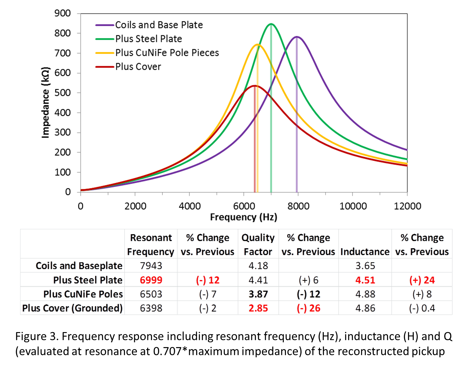
 I deconstructed a new reissue Fender Wide Range Humbucker with CuNiFe magnets. The component parts are shown in Figure 2. I stripped the pickup down to just the bobbins, coils and baseplate, all magnetically insignificant parts, although I suspect that the baseplate may have a significant effect on Q. The pickup was analyzed for impedance response as a function of frequency, and the inductance was measured at 20 Hz (the lowest available measurement frequency). The pickup was reconstructed, one piece at a time, and measured at each stage. The results are shown in Figure 3. As the data show, the single biggest influence on the pickup inductance (other than the coils themselves) is the steel plate, increasing the inductance of the assembly by almost 25%. The CuNiFe poles, in comparison, only contribute an 8% increase. The effect of the cover on inductance is negligible. The Q of the pickup is relatively unaffected by the presence of the steel plate, probably because it is not in the core of the coil. The most significant effect on Q comes, a bit surprisingly, from the cover. In most cases the effect of the cover (for instance, in a PAF-style humbucker) is measureable, but not nearly this significant. Perhaps this is because the material in the core of the core is of such low permeability that the cover has more of a relative effect. In any case, it could be argued that the steel plate is the single most important magnetic component of the pickup.

210502 Figure 3.png

210502 Figure 4.png
210502 Figure 5.png

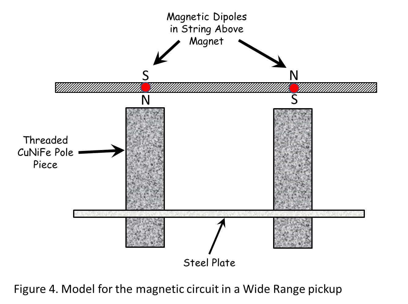
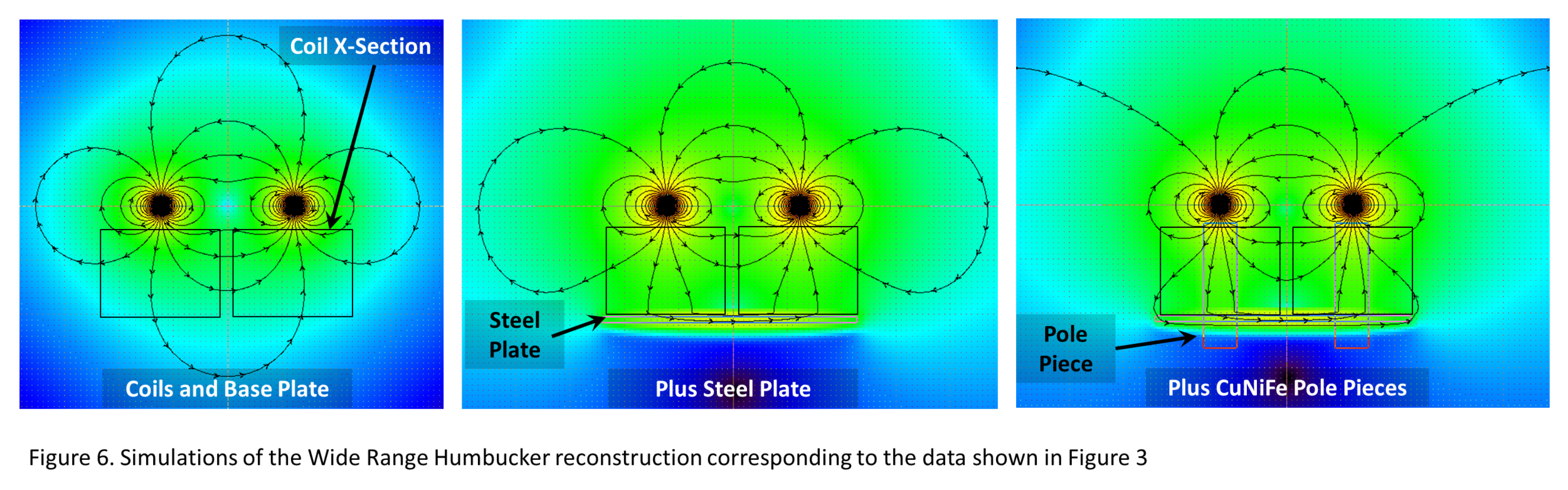
To understand why this would be, we can simulate the flux in the magnetic geometry of the pickup. Figure 4 shows a cross section of the pickup, and the geometry that is used as the magnetic model. Figure 5 highlights the part of the model to be focused on; in fact it’s the only part that matters in terms of signal generation, the part that goes through the volume encompassed by the coil. Only magnetic flux that passes within the envelope of a winding will generate a signal in the coil. Figure 6 gives the results of simulations corresponding to the pickup reconstruction sequence and data shown in Figure 3. With only the coils and base plate, the flux field from the string is unaffected, and is symmetric about the string. With the steel plate introduced, the flux field is pulled down towards the plate, expanding the field and generating a more uniform and stronger field in the volume encompassed by the coil, directly above the plate. The addition of the CuNiFe pole pieces results in only a slight concentration of flux in the poles, the general shape and density of the flux field in the volume of the coil is relatively unaffected. The cover is not modeled as it has no magnetic effect, at least none that can be modeled easily. The effects of materials on Q are complicated, but we will deal with them in a future blog post.

210502 Figure 6.png

By measurement and by simulation, CuNiFe has only a moderate effect on the frequency response and inductance of this pickup, but how does it compare to other materials? You’ll notice that 6 of the pole pieces are missing in Figure 2. Well, they were installed in a test Strat coil at the time. This is a reference coil (basically an empty coil from an import ceramic pickup assembly) that we use to compare pole piece materials. Figure 7 shows the impedance response as a function of frequency and the inductance for CuNiFe compared to AlNiCo 5, AlNiCo 2 and the stock steel pole pieces that were originally installed in the pickup. The empty coil is also shown for reference. CuNiFe imparts only about a 20% inductance increase and a very small change in resonant frequency. In fact, CuNiFe is less permeable (imparts a lower inductance increase) even than AlNiCo 5. As such, CuNiFe on its own would be 1) a very “weak” pole piece and 2) even more “transparent” than AlNiCo 5. Note that CuNiFe also exhibits the highest Q value of any of the materials.


210502 Figure 7.png

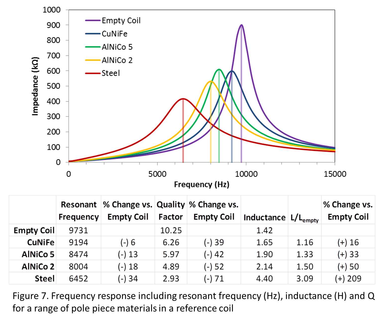
Figure 8 illustrates simulations of the effect of the permeability of the pole piece in the magnetic geometry of the Wide Range Humbucker. Note that the relative permeability of CuNiFe was set to 1.5 in the simulations illustrated in Figure 6. The relative permeability of AlNiCo 5 is around 2 and AlNiCo 2 is assumed to be 7. Steel is set here to 1000. As the figure illustrates, even small increases in permeability result in the flux field collapsing into the pole piece, disrupting the wider and more consistent flux field that is obtained with the lower permeability pole. So, we can see that even as the steel plate enables the wider field, CuNiFe, due to its almost total magnetic “transparency” in the flux field of the string, enables it to be maintained while also providing for the string to get magnetized. The combination of these material properties and their utilization in this efficient and innovative piece of engineering results in a pickup with a very unique magnetic structure, really one of a kind in pickup design.

And I have to believe that Seth Lover understood all of this. In fact, I have come to the conclusion that the “Wide Range” in the pickup name most specifically refers to the wider range of the flux field enabled by the large coils and especially the steel plate that spreads the field out to fill those coils. Not forgetting the CuNiFe which does not concentrate the field much at all, enabling it to remain spread out. He did this all very purposefully with the goal of a pickup that would match humbucker output and noise rejection performance with more of a Fender type of response. What he got met those goals, but it is really neither a PAF humbucker nor a Fender single coil, it’s a truly unique design that stands on its own.

210502 Figure 8.png

But, as mentioned in the intro, the Wide Range was discontinued in 1979 or so. Not particularly popular in its initial release, the design sat in the backwater of pickup history for many years. But like so many other things, people eventually started to develop an appreciation and a nostalgia for the design and demand for reproduction pickups grew. Early reproductions were less than authentic, mostly due to the unavailability of CuNiFe, and generally amounted to a PAF-style humbucker under a Wide Range cover. Eventually however, interest rose to the point that sources of CuNiFe were identified, and new manufacturing of CuNiFe was initiated, at least on a limited basis. Other permanently magnetic materials have been substituted for CuNiFe in otherwise faithful designs, most typically AlNiCo alloys or another magnet type that can be threaded (although even threaded AlNiCo has now become available) called FeCrCo. Figure 9 illustrates the frequency and inductive response of a range of Wide Range Humbucker reproduction pole piece materials measured in the reference strat coil. While they are all clustered in a range, CuNiFe exhibits the lowest permeability (as measured by the relative increase in inductance versus the reference coil) and the highest resonant frequency. FeCrCo alloys 5 and 2 are clustered adjacent to their respective AlNiCo “cousins”. FeCrCo exhibits the highest Q out of any of these alloys. These pole piece alloys would be expected to exhibit the behaviors simulated in Figures 6 and 8 based on permeability in the range of just over 1 to about 10. Any of these alloys will cause more of the magnetic flux to collapse into the core, compared to CuNiFe, so with any substitute some of the truly unique behavior that Seth Lover designed into this pickup will be lost. That being said, the differences in these alloys isn’t huge, and armed with this information the educated consumer (or even pickup designer) could tailor the design to different tastes. For instance, if you want to fatten it up a bit, go with the high permeability FeCrCo 2. Or perhaps use the high Q FeCrCo 5 to account for the typically higher resistance pot values (1 MΩ) that were originally mated with the Wide Range Humbucker. Another interesting thing about CuNiFe is that its electrical conductivity is about 3 times higher than any of the other alloys. This property means that it has a more significant eddy current effect than we might otherwise expect. But, that’s also a topic for a future blog.


210502 Figure 9.png

What strikes me about the genius of Seth Lover is how much he was able to understand and accomplish with so much more limited technological resources than we have now. It was just so much harder and more expensive to do anything back then, for one thing. Today, I can go take a full detailed and accurate measurement of a pickup in minutes (probably seconds if I wanted to spend a few thousand dollars and update my LCR meter), port the data (invirtual form, never having to transcribe anything) to my computer where I can import it into a spreadsheet and manipulate it in any number of different ways in seconds. In Lover’s day it would’ve taken a good part of a day just to take the measurements and make up a hand-drawn and plotted chart: oh and if you mess up the chart, get out the White-Out or do it all over again. In any event, in this or any other technological endeavor, it’s always good to remember that we stand on the shoulders of giants.

The LMP Z-Series™ Manifesto

Some changes are coming from Lawing Musical Products, the makers of Zexcoil® pickups.

We started this company about 7 years ago, after a preceding 2 or 3 years of development, to market our unique line of one-coil-per-string, hum-canceling pickups. We founded our company on a few underlying principles:

  1. A commitment to providing great products for the best price we could,

  2. A commitment to domestic supply and manufacturing, and

  3. A commitment to establishing a viable, independent and growing company that would help sustain us, as well as employ others, at a living wage.

We’ve learned a lot in these 10 years or so, both about the musical instrument business and about how to build great pickups. What we’re about to do now is borne out of both of those learnings.

We’ve come to realize that our relatively complicated pickup design is too expensive to produce, to the point that we can’t achieve all of our goals under the current paradigm. We needed to make some significant changes to how we produce these pickups to really become viable. What we’ve done is redesign the Zexcoil pickup to make it as inexpensive as we can. We’ve done this by eliminating redundant parts, commonizing parts where we could and streamlining the process required to build a pickup. As a result of this effort we have a less expensive pickup that retains the Core Zexcoil design, and because it’s inherently more efficient, sounds at least as good and in many ways better than our Legacy models. The only significant practical difference between our new Z-Series™ and Legacy™ Zexcoils is that the Z Series pickups are potted in their covers. This makes the Z-Series covers non-removable, while the Legacy pickups have interchangeable covers.

After much thought, we’ve also decided to continue with our direct internet business model. This allows us to cut out all of the middle men and give our customers the best possible price on these pickups. While we know that our superior performance can and always has commanded a premium, that’s not what this is about. It’s not about making as much money as possible. It’s about making enough money to be viable and sharing the benefits of our efficiencies with the end user as much as we possibly can.

So here’s what’s happening. Our model line and pricing structure will change significantly. We will be introducing the new Z Series pickups with the full range of analogs to our current Legacy models, and at the same time expanding our output range into the lower end of the scale, with new models that are closer to vintage pickup specifications than we have ever been.

Our Z-Core™ 5 family of pickups will be priced at $79.99. That’s 20% lower than any pickup we’ve offered to the general public before. The Z-Core product line represents pickups designed by us and assembled at our US partner factory, the same factory where our coils have always been wound. The initial Z-Core offerings will include our most popular voicings, with analogs to the Legacy SV5 and SV5O, and some new lower wind AlNiCo 5 voiced pickups that are closer to vintage single coil specs than anything we’ve ever made. These new lower wind sets are also designed for the same 250 kΩ controls that most conventional single coil equipped guitars use.

We will have a range of Custom Shop options based on the new Z-Series platform (including new Tele bridge pickups), with voicings analogous to our Legacy models, priced from $89.99 – 105.99. These Custom Shop models will include our 2, Fat 5, Convertible, Juicy and Throaty voicings. Custom Shop models will be built by us, and our handful of local builders, by hand. As demand warrants, we plan to migrate as many Z Series models as we can from the Custom Shop to the lower priced Z-Core line. Design and performance of Z-Series Custom Shop and Z-Core pickups are identical, the only difference being the economies of scale at which they are manufactured.

We will be offering a range of sets featuring 3 Z-Core 5s starting at only $225, and multiple options for mixed Z-Core/Custom Shop sets below $250. We also have Custom Shop Tele bridge/Z Core (Strat) neck sets starting at just $170.

We will continue to offer our Legacy product line through the Custom Shop, although the prices will be adjusted to reflect the realities of the costs involved in producing these pickups. We’ve designed the Z Series product line to cover all of the same bases as our Legacy pickups and there are Z Series analogs of just about every Legacy model. All of the new pickups incorporate the design concepts and philosophy of our Legacy products, in fact we believe that they represent the most advanced evolution of our approach to pickup design. The Z Series pickups are just a more efficient and streamlined version of the same great one-coil-per-string hum cancelling idea we’ve always had.

We will be raising the prices of our Legacy models to $129.00 with the full release of the Z-Core and Custom Shop Z-Series lines. We are targeting August 1, 2017 for the full release, and we will take orders for the Legacy models at the current prices up to that date.


Electrical Parameters and Pickup Performance, Part II - Inductance

In the first installment of this series I talked about Resistance, one of the most widely used pickup response parameters. Unfortunately, resistance is a parameter that is really only useful in the context of “all other things being equal”. If you change one thing about the design, you could affect pickup response significantly. Alternatively, you could design two pickups with different resistance that could be made to respond similarly.

In this post, I will discuss Inductance, a much more useful parameter than resistance. Inductance is the best descriptor of pickup output. As I demonstrated experimentally in an earlier blog post, How Does a Pickup Really Work?, pickups are after all just inductive sensors – converting the signal from the moving magnet (the vibrating, magnetized string) into an electrical impulse. Inductance is the measure of how effectively the pickup collects and converts that magnetic energy to electrical energy.

Electromagnetic induction is a fairly simple basic concept, the implications of which can get quite complicated. Figure 1 shows a classic example of electromagnetic induction, where the current in a coil produces a magnetic field which may then induce (hence, “Induction”) an electric field in a neighboring body. It is important to remember that magnetism and electricity are intertwined. Maxwell first showed how the two were related and years later Einstein showed that they were actually the same thing, the difference being merely the frame of reference of the observer. This is why with Electromagnetism as one of the 4 basic forces, we do not distinguish between them at the most fundamental level. So, not only will a current in a coil induce a magnetic field associated with the coil as in Figure 1, but a moving magnetic field will induce a current in a coil as well. Think of how electric motors work versus electric generators. They both utilize the same physics, just in reverse compared to each other. An electric motor generates motion through the laws of induction by applying a current, while a generator creates electricity through the laws of induction by harnessing motion.

A basic inductor, along with the governing equation for that inductor, is shown in Figure 2. This type of inductor, called a solenoid, consists of a single layer of conducting wire wrapped around a cylindrical core. The core may be empty (in which case we refer to it as an “air coil”) or it may be filled with, typically, a magnetically permeable material. Inductance is represented by the letter “L” (after Lentz) and is measured in “Henries”. From the equation, you can see that inductance depends linearly on a number of things including; the number of turns of wire that make up the coil (squared, so turns are huge), the area of the coil, the magnetic permeability µ (which we’ll discuss in a moment), and it depends inversely on the length of the coil. Magnetic permeability is a property of materials and it represents the tendency of a material to concentrate magnetic flux. For a material with high permeability, a magnetic field really wants to be in the material and it will basically suck the field in. Magnetic shielding typically has very high permeability and it effectively channels the magnetic field away from the object to be shielded (you can’t block a magnetic field, but you can redirect it). Materials with low permeability don’t tend to concentrate a magnetic field. For convenience, we usually talk about the relative permeability, µr, of a material. Relative permeability is defined such that the relative permeability of empty space (a “vacuum”) = 1. Air basically acts like a vacuum when we consider its magnetic properties, so an air coil is one in which the relative permeability of the core equals 1. A relative permeability of 1 basically does not affect a magnetic field at all, it’s like there is nothing there as far as the magnetic field is concerned. A material with a relative permeability greater than 1 will concentrate a magnetic field. A relative permeability less than 1 will reject a magnetic field.

So from the equation in Figure 2, we can see that relative permeability acts like a multiplier of inductance. A coil with a magnetically permeable core will theoretically have a higher inductance than a coil with a relative magnetic permeability of 1 by a factor of µr. Figure 3 shows what that looks like in terms of a guitar pickup. A guitar pickup is basically an inductor that is configured as a generator. The motion to the generator is supplied by the magnetized string. Remember, that for pickup function the only magnetic field we are concerned with is the field of the moving, magnetized string. The static field of the pickup doesn’t really matter, only that the string becomes magnetized. When plucked, the magnetized string projects a magnetic field that is associated with its vibration, and that vibration carries all of the tonal information of the note being played, the attack with which the note was struck, etc. As that magnetic field interacts with the pickup coil, an electrical signal is induced in the coil which also carries all of the information from the string pluck. That’s how the signal in an electric guitar is generated. As Figure 3 shows, with a low permeability pole piece like AlNiCo5, which has a magnetic permeability barely higher than air and is the most used pole piece in a Strat style single coil pickup, the field of the string is not really affected, it blooms out from the string in a fairly symmetric pattern. With a high permeability pole piece, like the low carbon steel typically used as the screws and slugs in a humbucker, the field from the magnetized string is distorted, and effectively drawn into the pole piece, becoming concentrated in the core of the coil.

Now go back and take a close look at Figure 1. Note that when the magnetic field is created by the current in the coil, the field lines are centered about the coil and are concentrated in the core of the coil. Every field line created by the current in the coil passes through the center of the coil. So for the opposite case, where we want to induce a current in the coil via an external magnetic field, the field lines that will be most efficient in generating that current will be the ones that pass through the core of the coil. This is the physical reason why magnetic permeability is so important in increasing inductance. A permeable material in the core of the coil acts to concentrate the magnetic field exactly where it needs to be in order to make the inductor more efficient.

But why don’t we get all of the benefit of the magnetic permeability in a guitar pickup? If permeability is a multiplier of inductance, shouldn’t a pickup with a pole piece with 2000 times the permeability of air have an inductance 2000 times the air coil? Why only by a factor of about 6 as shown in Figure 3? First, we have to consider that magnetic energy travels in loops, just like electrical energy. The black lines in Figures 1 and 3 represent the paths taken by representative loops in the magnetic field. The problem with the “magnetic circuit” depicted in Figure 3 is, while the core of the coil is filled with magnetically permeable material, most of the magnetic circuit is air. For the full multiplying potential of the permeable material to be realized, we must construct a closed magnetic loop, as shown at left in Figure 4, where virtually all of the magnetic flux is contained in a closed loop of permeable material. Note that all of the field lines are contained in the rectangular loop of permeable material. Even a fairly short air gap, as shown in the middle of Figure 4, can result in as much as a 99% loss of the native permeability of the core material. Notice how the field lines start fringing out significantly into the low permeability space around the permeable core, even on the opposite side from the air gap. A pickup is basically a completely open magnetic circuit as shown at right in Figure 4, where the field is free to bloom out into the low permeability space. Considering what happens to the field lines in the examples shown in Figure 4, we can start to see how other permeable materials in the pickup, baseplates, covers, etc., might also affect the field and the effective inductance and response of the pickup. Of course, as shown by Figure 1, the most important material is the stuff in the core of the coil.

But what does this mean for pickup design and response? Here’s an example of the effect of the area of the coil coupled with the magnetic permeability of the pole piece material. Figure 5 illustrates the inductance as a function of turn count squared (according to the proportionality shown in the equation in Figure 2) for a range of coils using 41 awg (closed symbols) and 42 awg copper wire. The coils are measured as air coils (i.e. nothing in the core of the coil but air), with an AlNiCo 5 pole piece and with a nickel plated low carbon steel pole piece. As I’ve mentioned a few times, we use a range of coil gauges in Zexcoil® pickups, and we basically use the largest diameter (lowest gauge) wire we can at any given turn count. When we fill up the bobbin we jump to the next wire gauge. So, the highest turn count coil for a given gauge will be as big as the coil can get, we’re basically filling the bobbin up completely. Then the next highest turn count coil, with the next smallest gauge wire, will be significantly smaller and encompass less coil area even though it has more turns. As we can see from Figure 5, with an air coil we can very clearly see this effect. There is a discontinuity in the relationship between turns and inductance every time we “jump” to the next gauge. The larger wire at the highest turn counts is yielding more inductance per turn than the smaller wire. If we put a pole piece in the core of the coil with minimal magnetic permeability, like AlNiCo 5, we still see an area effect but it is reduced. If we put a highly magnetically permeable pole piece in the core, like low carbon steel, the area effect goes away entirely. With a highly permeable core, the magnetic flux becomes so concentrated that it doesn’t really matter exactly how much area the turn encompasses, as long as it’s going around the concentrated flux in the core. The effective area of any given turn becomes the area of the core because that’s where virtually all of the magnetic flux is.

And finally, what does this mean for the player? How can an understanding of inductance help with pickup selection? Well, for one thing since inductance is directly related to how efficient a pickup is in capturing magnetic energy, it is a much better and more direct measure of output than resistance. That’s probably the most important thing for the player to remember, and to try and interpret the number in relation to their known reference points. Table 1 lists some of the typical specifications for a few of the more popular pickup types, representing a range of some of the original designs. With the rise of aftermarket pickup makers, the specification range of all of these designs has expanded considerably from what is represented in the table, which characterizes the “classic” interpretations of these designs. First we have the Stratocaster® pickup. The Strat® pickup uses low permeability AlNiCo 5 pole pieces, and a coil wrapped around those poles consisting of 7500 – 8500 turns. This yields typical resistances in the range of 5500 – 6500 Ohms (5.5 – 6.5 kOhms) and inductances in the range of 2.3 – 3.0 Henries. Next is the PAF. A PAF consists of two coils, roughly the same size as the Strat’s coils, except the PAF uses high permeability steel pole pieces – slugs in one coil, screws in the other. Each coil of the PAF is wound to something in the range of 5500 – 6500 turns yielding a typical resistance of around 7000 – 9000 Ohms with the coils wound in series (resistance adds in series). Even though the PAF is wound only slightly higher than a Strat style single coil, the more permeable steel pole pieces result in a significantly higher inductance, in the range of 4.0 – 5.0 Henries. Finally, the P90 is a single coil design that utilizes steel pole pieces and a shorter and fatter coil than the Strat-style pickup. One thing to keep in mind is that in a conventional pickup design with individual pole pieces much of the core of the coil is air, unlike in a Zexcoil where most of the core is filled with the pole piece. So, as in a P90 where the pole pieces are fairly narrow screws, only about 25% or less of the core is actually occupied by the permeable material, so the effective permeability will be much less than what we would expect based on steel alone. Accordingly, you can see a significant effect of the area of the coil on the P90 response. At a turn count that is more or less the same as a PAF and with a similar (or even lower) effective permeability in the core, the P90 yields a much higher inductance due to the larger area encompassed by the turns. We could also surmise that the area effect would be more significant on a Strat-style pickup than say, a PAF at similar coil dimensions, because of the much lower permeability AlNiCo 5 pole pieces. This is certainly one of the reasons that things like insulation type and winding technique, which one might otherwise assume would be fairly subtle effects, can have an audible impact on the response of these types of designs. Looking again at Figure 4, we can also start to imagine how other permeable masses in the magnetic return path to the string, like the magnets in PAF pickups, have an effect. On that point, I’d like to reiterate, the important field in terms of how a pickup generates signal is the field of the string, not the magnetic field of the pickup itself. The solenoids depicted in Figures 1 and 4 show the field generated by a current in a coil, and because of that the field is necessarily enveloping the coil. While these figures help to understand the basic concepts of inductance and to highlight why pole piece properties are important, and they are not dissimilar to the way you generally see the magnetic field of the pickup depicted in descriptions of electric guitar function, they don’t represent the way signal is generated in a pickup. The way a pickup functions is depicted in Figure 3, as a receiver of the magnetic flux generated by the moving, magnetized string. If this statement causes you pause, I suggest you read this blog post.

Electrical Parameters and Pickup Performance, Part I - Resistance

In the course of developing the Zexcoil hum canceling format, I was faced with some insurmountable engineering problems with the materials that are conventionally used in Strat-style single coil pickups. As I have been explaining, the pole piece is primarily responsible for defining the timbre of a passive electric guitar pickup, and in the case of single coils it is the electromagnetic properties of AlNiCo alloys (and most specifically AlNiCo 5) that define the classic Strat tone. The problem was, AlNiCo alloys don’t work very well in the Zexcoil format because they can’t effectively close the magnetic dead spot between the D and G strings (where the magnetic polarity flips so we can get hum canceling). So I was forced to develop an understanding of what it was exactly that caused AlNiCo alloys to “sound” like they do and how I could get the same response from different materials, materials capable of closing the magnetic seam.

We think we were successful in solving the problem, but we’ll let you judge that by your impressions of our pickups. What we also got though, was a physical model for the electro-magnetic response of pole piece materials that basically allows us to create a map of tonal characteristics. We use this map in the design of all of our pickups. Since this is a basic model, the general responses are not limited to Zexcoil pickups, and pickup performance in general can be interpreted in the same context.

But we’ve struggled with how to make that information accessible to players to the extent that they can use it to guide their own pickup choices. We’re going to try some new things coupled with the roll out of our Z-Core™ and Z-Series™ models this summer. One of the things we’re going to do is provide a lot of the electrical specs for the various models.

In order for that information to be useful, it’s necessary to place the raw numbers in a tonal context. Resistance, Inductance, Resonant Frequency, Quality Factor, that’s all great: but what does it SOUND like? We’re going to attempt to answer that question, or at least provide some good guidance that might allow players to interpret the electrical specs more easily. We’ll start here by discussing the electrical parameters that we consider critical and describing what they are and what they mean in a terms of pickup performance.

First, the most ubiquitous electrical specification in use today, and by most accounts the most meaningless, Resistance. Electrical resistance is exactly what it sounds like; it’s the tendency of a material to resist electric current. Resistance is measured in Ohms, the symbol for which is “Ω”. Sometimes you’ll see a “k” in front of the“Ω”, and this means multiply by 1,000. So for example, 250 k Ω is the same as 250,000 Ω, it’s just shorthand.  In almost all electric guitar pickups, resistance is a function of only two things; 1) the total length of wire that encompasses the pickup’s coils and 2) the gauge (or more accurately: thickness) of that wire. You can think of resistance like the width and length of a pipe that you are trying to pump water through. The narrower and longer the pipe, the harder it is to push to get the water through. So then, the thicker the wire (or the lower the gauge number), the lower the electrical resistance. The longer the wire, the higher the electrical resistance.

Most Strat style single coil pickups use an identical design and dimensions, the same 42 awg copper wire and similar AlNiCo 5 pole pieces. In this limiting case of “all other things being equal”, resistance actually is a pretty good descriptor of pickup performance. That’s one reason that it has become so widely used. But, change one thing and it starts to get a lot less meaningful. Change the wire gauge, and the resistance for the same length of wire changes. Change the pole piece and the output will change, even at the same resistance (we’ll talk about some of those effects in the next blog post on Inductance). Even change the material used for the wire, say from copper to silver as in the Seymour Duncan Zephyr pickup, and resistance will change at the same length of wire since resistivity (resistance per unit volume) is a property of the material and silver is a better conductor, in that it has inherently lower resistivity than copper.

So, resistance is not a great number as an absolute measure of pickup response. In the Zexcoil format, we pretty much use the fattest wire we can for any given winding level, and we may use 2 or 3 different wire gauges in a single pickup to get them tuned where they need to be given our unconventional magnetics. Resistance also represents a loss of efficiency, and in keeping with our over-arching philosophy of maximizing efficiency, we basically try to keep the resistance as low as possible for any given design.

Pickup Resistance and Pot Values

One place where resistance does become important is in how the pickup interacts with the controls. The simplest way to think about a potentiometer (“pot”) in a guitar is as a gate. A typical guitar control is just a variable resistor in a circular format. The knob turns a wiper that is contacting a semi-circular resistive strip, with one end of the strip connected to ground. When on “10”, the full resistance of the pot blocks the path to ground.  When the pot is set to “0” that block is removed, and pretty much all of the signal goes to ground and we get no volume. When the pot is on “10”, most of the signal is retained, but some of the higher frequencies can manage to sneak through the pot and get lost to ground. The higher the value of the pot, relative to the pickup, the less high end is lost. Go back to the water analogy. Think about the volume pot/pickup system as a garden hose with a pin hole in it. The water coming out of the nozzle at the end of the hose is like the signal going out to the amp. With a small pin hole in the hose, almost all of the water in the hose still comes out the nozzle, but just a little bit of spray will escape through the pin hole. That spray is like the high end being lost through the volume pot. A 250 k pot versus a 500 k pot is like a bigger hole in the hose so more spray is lost. A volume pot on zero is like a hole in the hose big enough so that all of the water comes out the hole and none makes it to the nozzle. Strat style single coils, with resistances on the order of 5,000 Ohms or so, generally use 250 kΩ pots. Hum buckers, which typically have higher resistance than single coils – approaching 10,000 Ω, are usually better balanced with 500 kΩ pots. A good rule of thumb is that the pot value should be 25-50x the value of the pickup.

We refer to this scenario of attaching a resistance along with the pickup as “loading”. Tone pots (at “10” anyway, when you start dialing down the resistance of the tone pot, the tone capacitor comes in to play and things get a lot more complicated) represent a similar “load” on the pickup as a volume pot. In fact, when you have both a 250 kΩ volume and tone pot connected the effective resistance to ground is only 125 kΩ, so more signal (highs go first remember) can bleed over the lower barrier. A “No Load” tone pot is one in which there is a physical break in the resistive strip just below “10” on the dial. When the wiper is in the “10” position then, the pot is disconnected from ground and the load is removed. With a no load tone pot on “10” the only path to ground is through the volume pot. This has the audible effect of maintaining more of the high end “air”, and the tone will darken up noticeably when the tone pot is engaged just below “10”, especially through a clean amp. Go back again to the water analogy. A no load pot is like putting a bandage over the pin hole when the pot is on “10”, so the hole in the hose is plugged up and the spray is not allowed to escape. Just below “10”, as the resistive strip is engaged, it’s like the bandage has been removed and the spray through the pin hole is allowed out. We like to use no load pots on the neck and bridge positions, and we especially like the way they open up the “in between” positions. For most typical control layouts, the bridge pickup can benefit from tone pot loading, so we don’t use them much there. One exception would be the Convertible for Bridge where we like to use the no load tone as a “load toggle” between the two modes; unloaded for the higher resistance series mode to let all of the power come through and loaded down a bit more to attenuate the highs on the lower resistance parallel mode.